Scraping and grinding of guide bearing bush and thrust bush of small hydraulic turbine is a key process in the installation and repair of small hydropower station.
Most of the bearings of small horizontal hydraulic turbines have no spherical structure and thrust pads have no anti weight bolts. As shown in the figure: A is aspheric structure; B is no anti weight bolt, and the thrust pad is directly pressed on the pad frame. The following is mainly to talk about the methods, steps and requirements of scraping and installation for this structural form.
1. The preparation tools are triangle and double-sided oilstone. The length of triangular setback can be adjusted according to your own habits. Generally, it is appropriate to use 6-8 o’clock. The old triangular setback can also be reformed. If possible, you can also use spring steel to hit one or two flat knife, which is more convenient to scrape the thrust pad. The rough grinding of triangular setback is carried out on the grinding wheel. During grinding, it shall be fully cooled with water to prevent the triangular setback from heating and annealing softening. Fine grinding is carried out on the oilstone to remove the very fine dents and burrs left during coarse grinding. During fine grinding, engine oil (or turbine oil) shall be added for cooling. Prepare the clamp table with appropriate height. The display agent can be mixed with smoke ink and turbine oil or printed red.
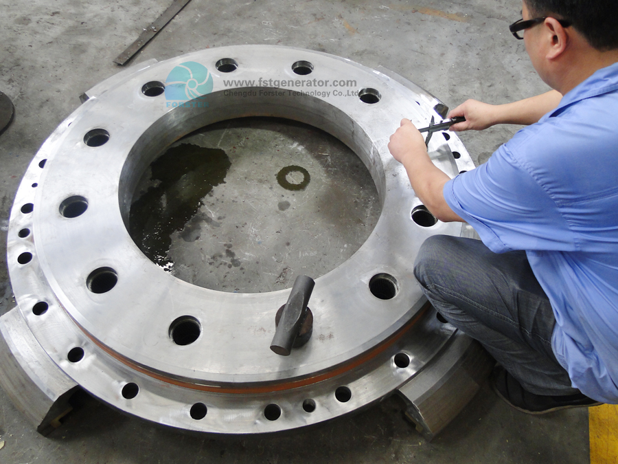
2. Cleaning, derusting and deburring. The bearing shall be derusted and deburred before scraping. In particular, the combination surface of the guide bearing bush, the bearing joint surface of the bearing and the bearing surface of the thrust pad shall be carefully cleaned.
3. Rough scraping of bearing bush. Firstly, the main shaft of the turbine shall be leveled and fixed, (levelness ≤ 0.08m / M) to prevent the shoe from being scratched into a taper shape. Gently and evenly plane the whole bearing surface with a triangular knife to remove the sand and impurities attached to the bearing surface. Impurities deeply trapped in the bearing alloy shall be picked out to avoid affecting the quality of scraping pad.
After cleaning the journal, hold the guide bearing bush on the journal, fix the locating pin, lock the screw, and measure the combined surface of the bearing bush and the gap between the Bush and the journal with a feeler gauge to determine the thickness of copper sheet added on the combined surface (padding is for future maintenance). – Generally, the copper pad is double-layer, and about 0.10 ~ 0.20mm can be added. The principle for determining the total thickness of the pad is to leave a scraping allowance of 0.08 ~ 0.20 for the bearing bush; On the one hand, the scraping quality should be guaranteed, on the other hand, the workload of scraping tiles should be reduced as much as possible.
Place the cut copper sheet on the joint surface of the bearing bush, hold the two bearing bushes on the journal, tighten the fixing screws, rotate the bearing bush and grind it. If it cannot be rotated, remove the bearing bush, buckle it in half on the journal, press it by hand, grind it back and forth along the tangent direction, and then hug and grind it when there is a gap between the bearing bush and the journal. After grinding, the contact part of the tile surface will show black and bright, and the higher part will be black but not bright. Cut off the black and bright part with a triangular setback. When the bright black spots are not obvious, apply a layer of display agent on the journal before grinding. Grind and scrape repeatedly until the contact and clearance between the bearing surface and the journal meet the requirements. Generally speaking, the whole tile surface should be contacted at this time, but there are not too many contact points; The clearance has begun to approach the requirements, and there is a scraping allowance of 0.03-0.05mm. Scrape the bearing shells on both sides of the flywheel respectively.
4. Scraping of thrust pad. Because the thrust pad is often scratched during transportation and preservation, there will be burrs on the pad surface, so first stick the metallographic sandpaper to the mirror plate, and push the thrust pad back and forth on the sandpaper for several times. During grinding, keep the tile surface parallel to the mirror plate, and the grinding times and weight of each tile are the same, otherwise the thickness of thrust varies greatly, increasing the workload of scraping.
Wipe the mirror plate and the pad surface, press the thrust pad on the mirror plate, grind it back and forth for more than ten times according to the rotation direction of the pad and the mirror plate, and remove the thrust pad for scraping. After all the bearing surfaces are in good contact with the mirror plate, the bearing can be assembled
5. Bearing assembly and fine scraping. First, put the cleaned bearing seat in place (on the foundation frame, the fixing screws of the bearing seat can be connected in series but not tightened), put the lower bearing bush into the bearing seat, gently lift the large shaft into the bearing bush, adjust the bearing seat by measuring the bearing bush clearance, so that the center line of the bearing bush on both sides of the flywheel is in a straight line (top view: general error ≤ 2 wires), and the front and rear positions are appropriate (cushion shall be added when the height difference of the bearing seat is large), and then lock the fixing screw of the bearing seat.
Manually rotate the flywheel for several turns, remove the bearing bush and check the distribution of bearing bush contact points. When the whole bearing surface has good contact and the bearing bush clearance basically meets the requirements (the clearance shall comply with the requirements of the drawing. If it is not indicated, take 0.l ~ 0.2% of the journal diameter for scraping. Scrape the large points with a triangular file and dilute the dense points; the knife pattern is generally strip, which is used to facilitate the storage and circulation of turbine oil. The requirement is that the contact points are fully distributed within the included angle of 60 ° ~ 70 ° in the center of the lower bearing bush, and 2-3 points per square centimeter is appropriate, not too much or too little.
Clean the thrust pad with a white cloth. After it is in place, add a little lubricating oil to the guide bearing pad, rotate the flywheel, and add an axial thrust to grind the thrust pad and the mirror plate according to its actual position. Mark each pad (the position of the thrust pad with temperature measuring hole and close to the combination surface is fixed), check the pad surface, scrape the contact pad again, and evenly grind the pin on the back of the pad with abrasive cloth (the grinding is much lower, which shall be measured with inner diameter micrometer or vernier caliper, which is compared with the thinner pad). On the one hand, the purpose is to make the pad surface better contact with the mirror plate, on the other hand, to make the “thick” thrust pad thinner. It is required that all 8 thrust pads have good contact in the actual position. Generally speaking, the thrust pad of horizontal small turbine is small and the load is small, so the pad surface can not be scratched.
6. Fine scraping. After the whole bearing is installed in place and the concrete hardens, add axial thrust to turn, and repair and scrape according to the actual contact between bearing pad and thrust pad to meet the requirements of drawings and specifications.
A longitudinal oil groove shall be opened on both sides of the joint of the bearing bush or on one side (oil supply side), but at least 8mm heads shall be reserved at both ends to avoid the loss of lubricating oil from both ends. The oil inlet of the push pad generally includes 0.5mm lower and the width is about 6 ~ 8mm. The bearing bush and thrust pad are qualified only after fine scraping
Post time: Dec-13-2021
