20ft 250KWh 582KWh Containerized Lithium-ion Battery Energy Storage Systems


Description of Lithium-ion Battery Energy Storage Systems
| Name | Specification | Packing List |
| Containerized Lithium-ion Battery Energy Storage Systems | Standard 20ft container | Including battery system, air conditioning, fire protection and all connecting cables in the container, PCS, energy management system EMS. |
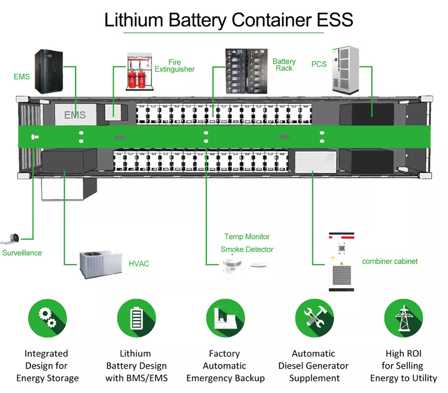
(1) The energy storage system is composed of lithium iron phosphate battery cabinet, PCs, control cabinet, temperature control system and fire protection system, which are integrated in a 20 foot container. It includes 3 battery cabinets and 1 control cabinet. The system topology is shown below
(2) The battery cell of the battery cabinet is composed of 1p * 14s * 16S series and parallel mode, including 16 lithium iron phosphate battery boxes and 1 main control box.
(3) The battery management system is divided into three levels: CSC, sbmu and mbmu. CSC is located in the battery box to complete the data acquisition of the information of individual cells in the battery box, upload the data to sbmu, and complete the equalization between individual cells in the battery box according to the instructions issued by sbmu. Located in the main control box, the sbmu is responsible for the management of the battery cabinet, receiving the detailed data uploaded by the CSC inside the battery cabinet, sampling the voltage and current of the battery cabinet, calculating and correcting the SOC, managing the pre charge and charge discharge of the battery cabinet, and uploading the relevant data to the mbmu. Mbmu is installed in the control box. Mbmu is responsible for the operation and management of the whole battery system, receives the data uploaded by sbmu, analyzes and processes it, and transmits the battery system data to PCs. Mbmu communicates with PCs through can communication mode. See Appendix 1 for communication protocol; Mbmu communicates with the upper computer of the battery through can communication. The following figure is the communication diagram of the battery management system
Operating Conditions of The Energy Storage System
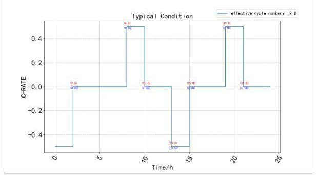
The design maximum charge rate and discharge rate do not exceed 0.5C. During testing and use, Party A is not allowed to exceed the charging and discharging rate and operating temperature conditions stipulated in this agreement. If it is used beyond the conditions specified by Party B, Party B will not be responsible for free quality assurance of this battery system. In order to meet the technical requirements of the number of cycles, the system requires no more than 0.5C for charging and discharging, the interval between each charging and discharging is more than 5 hours, and the number of charging and discharging cycles within 24 hours is no more than 2 times. The operating conditions within 24 hours are as follows
Lithium-ion Battery Energy Storage Systems Parameter
| Rated Discharge Power | 250KW |
| Rated Charging Power | 250KW |
| Rated Energy Storage | 582KWh |
| System Rated Voltage | 716.8V |
| System Voltage Range | 627.2~806.4V |
| Number Of Battery Cabinets | 3 |
| Battery Type | LFP battery |
| Maximum Operating Temperature Range (Charging) | 0~54℃ |
| Maximum Operating Temperature Range(Discharge) | “-20~54℃ |
| Container Specification | 20ft |
| Auxiliary Power Supply Of Container | 20KW |
| Container Size | 6058*2438*2896 |
| Container Protection Grade | IP54 |
Battery Monitoring System
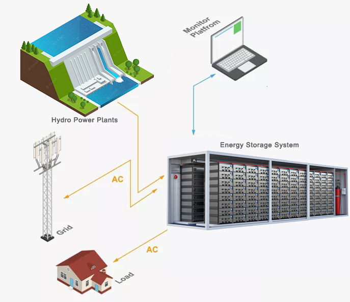
The project is equipped with a set of local monitoring system to complete the comprehensive monitoring and operation / control of the whole energy storage system. The local monitoring system needs to control the temperature of the container according to the on-site environment, adopt appropriate air conditioning operation strategies, and reduce the energy consumption of the air conditioner as much as possible on the premise of maintaining the battery in the range of normal storage temperature. The local monitoring system and energy management system use Ethernet to communicate through Modbus TCP protocol to transmit BMS, air conditioning, fire protection and other alarm information to the station level energy management system.
