Composite materials are making inroads in construction of equipment for the hydroelectric power industry. An investigation into material strength and other criteria reveals many more applications, particularly for small and micro units.
This article has been evaluated and edited in accordance with reviews conducted by two or more professionals who have relevant expertise. These peer reviewers judge manuscripts for technical accuracy, usefulness, and overall importance within the hydroelectric industry.
The rise of new materials provides exciting opportunities for the hydroelectric industry. Wood — used in the original waterwheels and penstocks — was supplanted in part by steel components in the early 1800s. Steel retains its strength through high fatigue loading and resists cavitation erosion and corrosion. Its properties are well-understood and the processes for component manufacture are well-developed. For large units, steel will likely remain the material of choice.
However, given the rise of small (below 10 MW) to micro-sized (below 100 kW) turbines, composites can be used to save weight and reduce manufacturing cost and environmental impact. This is especially relevant given the continuing need for growth in electricity supply. The installed world hydro capacity, nearly 800,000 MW according to a 2009 study by Norwegian Renewable Energy Partners, is only 10% of the economically feasible and 6% of the technically feasible hydropower. The potential to bring more of the technically feasible hydro into the realm of economically feasible increases with the ability of composite components to provide economy of scale.
Composite component manufacture
To manufacture the penstock economically and with consistent high strength, the best method is filament winding. A large mandrel is wrapped with tows of fiber that have been run through a resin bath. The tows are wrapped in hoop and helical patterns to create strength for internal pressure, longitudinal bending and handling. The results section below shows the cost and weight per foot for the two penstock sizes, based on a quote from local suppliers. The quote showed that the design thickness was driven by installation and handling requirements, rather than the relatively low pressure load, and for both it was 2.28 cm.
Two manufacturing methods were considered for the wicket gates and stay vanes; wet layup and vacuum infusion. Wet layup uses dry fabric, which is impregnated by pouring resin over the fabric and using rollers to push the resin into the fabric. This process is not as clean as vacuum infusion and does not always produce the most optimized structure in terms of fiber-to-resin ratio, but it takes less time than the vacuum infusion process. Vacuum infusion lays up dry fiber in the correct orientations, and the dry stack is then vacuum bagged and extra fittings are attached that lead to a resin supply, which is drawn into the part when the vacuum is applied. The vacuum helps maintain the amount of resin at an optimal level and reduces the release of volatile organics.
The scroll case will use a hand layup in two separate halves on a male mold to ensure a smooth inner surface. These two halves will then be bonded together with fiber added to the outside at the bonding point to ensure adequate strength. The pressure load in the scroll case does not require a high-strength advanced composite, so a wet layup of fiberglass fabric with an epoxy resin will be sufficient. The thickness of the scroll case was based on the same design parameter as the penstock. The 250-kW unit is an axial flow machine, so there is no scroll case.
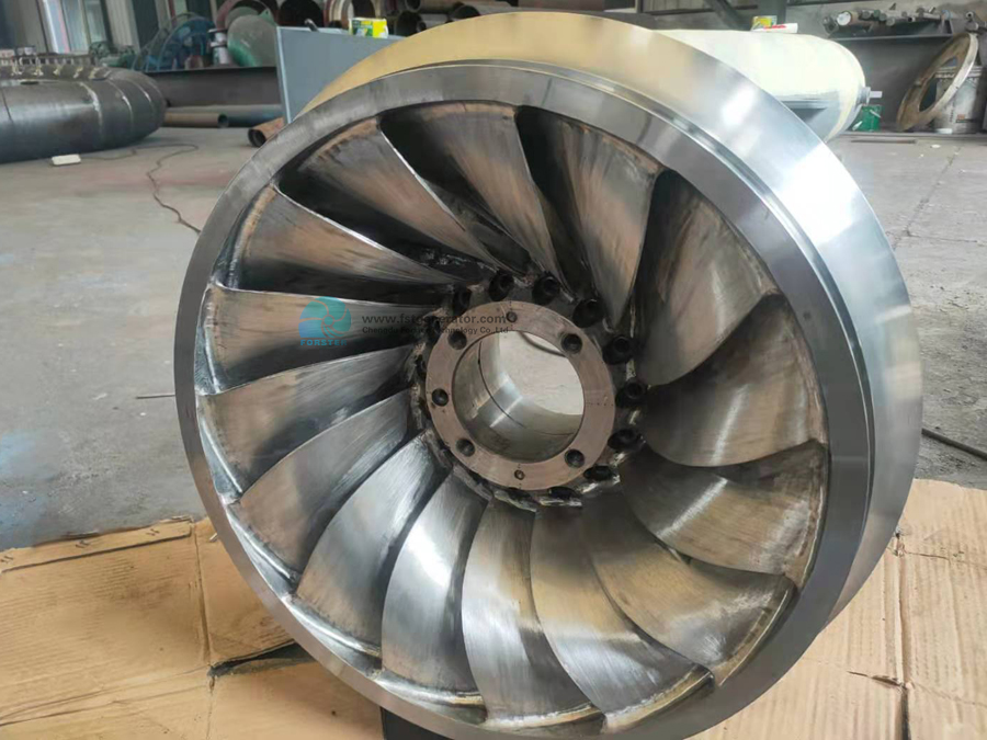
A turbine runner combines a complex geometry with high load requirements. Recent work has demonstrated that high-strength structural components can be manufactured from a chopped prepreg SMC with excellent strength and stiffness.5 The suspension arm of the Lamborghini Gallardo was designed using multiple layers of a chopped prepreg SMC known as a forged composite, compression molded to produce the required thickness. The same method can be applied to the Francis and propeller runners. The Francis runner cannot be made as one unit, as the complexity of the blade overlap would prevent the part from being extracted from the mold. Thus, the runner blades, crown and band are manufactured separately and then bonded together and reinforced with bolts through the outside of the crown and band.
While the draft tube is most easily manufactured using filament winding, this process has not been commercialized using natural fibers. Thus, hand layup was chosen, as this is standard method of manufacture, despite the higher labor costs. Using a male mold similar to a mandrel, the layup can be completed with the mold horizontal and then turned vertical to cure, preventing sagging on one side. The weight of the composite parts will vary slightly depending on the amount of resin in the finished part. These numbers are based on 50% fiber weight.
The total weights for the steel and composite 2-MW turbine are 9,888 kg and 7,016 kg, respectively. The 250-kW steel and composite turbines are 3,734 kg and 1,927 kg, respectively. The totals assume 20 wicket gates for each turbine and a penstock length equal to the head of the turbine. It is likely that the penstock would be longer and require fittings, but this number gives a basic estimate of the weight of the unit and associated peripherals. The generator, bolts and gate actuating hardware are not included and are assumed to be similar between the composite and steel units. It is also worth noting that the runner redesign required to account for stress concentrations seen in the FEA would add weight to the composite units, but the amount is assumed to be minimal, on the order of 5 kg to strengthen points with stress concentration
With the given weights, the 2-MW composite turbine and its penstock could be lifted by the fast V-22 Osprey, whereas the steel machine would require a slower, less maneuverable Chinook twin rotor helicopter. Also, the 2-MW composite turbine and penstock could be towed by an F-250 4×4, whereas the steel unit would require a larger truck that would be difficult to maneuver on forest roads if the installation was remote.
Conclusions
It is feasible to construct turbines from composite materials, and a weight reduction of 50% to 70% was seen compared to conventional steel components. The reduced weight can allow composite turbines to be installed in remote locations. In addition, assembly of these composite structures does not require welding equipment. The components also require fewer parts to be bolted together, as each piece can be made in one or two sections. At the small production runs modeled in this study, the cost of the molds and other tooling dominate the component cost.
The small runs indicated here show what it would cost to begin further research into these materials. This research can address cavitation erosion and UV protection of the components after installation. It may be possible to use elastomer or ceramic coatings to reduce cavitation or ensure that the turbine runs in the flow and head regimes that prevent cavitation from occurring. It will be important to test and resolve these and others issues to ensure the units can achieve similar reliability to steel turbines, especially if they are to be installed in areas where maintenance will be infrequent.
Even at these small runs, some composite components can be cost-effective due to the decreased labor required for manufacture. For example, a scroll case for the 2-MW Francis unit would cost $80,000 to be welded from steel compared to $25,000 for composite manufacture. However, assuming successful design of turbine runners, the cost for molding the composite runners is more than equivalent steel components. The 2-MW runner would cost about $23,000 to manufacture from steel, compared to $27,000 from composite. Costs may vary by machine. And the cost for composite components would drop considerably at higher production runs if molds could be reused.
Researchers have already investigated the construction of turbine runners from composite materials.8 However, this study did not address cavitation erosion and the feasibility of construction. The next step for composite turbines is to design and build a scale model that will allow proof of feasibility and economy of manufacture. This unit can then be tested to determine efficiency and applicability, as well as methods for preventing excess cavitation erosion.
Post time: Feb-15-2022
