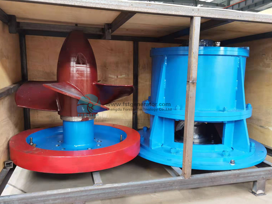
Hydrogenerators can be divided into vertical and horizontal types according to their axis positions. Large and medium-sized units generally adopt vertical layout, and horizontal layout is usually used for small and tubular units. Vertical hydro-generators are divided into two types: suspension type and umbrella type according to the support mode of guide bearing. Umbrella water turbine generators are divided into ordinary umbrella type, half umbrella type and full umbrella type according to the different positions of the guide bearing on the upper and lower frame. Suspended hydro-generators have better stability than umbrellas, with smaller thrust bearings, less loss, and convenient installation and maintenance, but they consume a lot of steel. The total height of the umbrella unit is low, which can reduce the height of the powerhouse of the hydropower station. Horizontal hydro-generators are generally used in situations where the speed is greater than 375r/min, and some small-capacity power stations.
The generator is a vertical suspension type, divided into two types: radial closed circulation ventilation and open duct ventilation. The entire air path is calculated and designed through ventilation and heat dissipation calculation software. The air volume distribution is reasonable, the temperature distribution is uniform, and the ventilation loss is low; The machine is mainly composed of stator, rotor, upper frame (load frame), lower frame, thrust bearing, upper guide bearing, lower guide bearing, air cooler and braking system. The stator is composed of a base, iron core and windings.

So as to ensure the provision of F-class insulation system with excellent performance and reliable operation. The rotor is mainly composed of magnetic poles, yokes, rotor supports, shafts, etc. The structure of the rotor and the selected materials can ensure that the motor is not damaged and does not produce harmful deformation during operation under various working conditions and maximum runaway. The thrust bearing and the upper guide bearing are placed in the oil groove of the center body of the upper frame; the lower guide bearing is placed in the oil groove of the center body of the lower frame. Bearing the combined load of the weight of all rotating parts of the hy
dro-generator set and the axial water thrust of the hydro-turbine, the guide bearing bears the radial load of the generator. The generator and the main shaft of the turbine are rigidly connected.
Post time: Nov-19-2021
