Hydraulic turbines are the heart of hydropower plants, converting the kinetic and potential energy of flowing water into mechanical rotation, which in turn drives generators to produce electricity. As the world seeks sustainable and reliable energy sources, the design and production of these sophisticated machines have become more critical than ever. This article delves into the intricate process of bringing a hydraulic turbine from concept to reality.
Part 1: The Design Phase – Where Engineering Meets Nature
The design of a hydraulic turbine is a complex, multi-disciplinary endeavor that balances fluid dynamics, material science, structural mechanics, and environmental considerations. It begins with a fundamental question: What type of turbine is best suited for the site?
1.1 Turbine Selection: Matching the Machine to the Resource
The choice of turbine is primarily dictated by the site’s head (the height water falls) and flow rate.
Impulse Turbines (Pelton Wheel): Ideal for high-head, low-flow applications. In a Pelton turbine, high-velocity jets of water strike spoon-shaped buckets mounted on the runner, transferring momentum. The design focuses on optimizing bucket geometry to capture the maximum energy from the jet.
Reaction Turbines: Utilize both the velocity and pressure of water. They are submerged in the water flow.
Francis Turbine: The workhorse of hydropower, suitable for a medium-head, medium-flow range. Its design features a radial-inflow runner with fixed guide vanes (stay vanes) and adjustable wicket gates to control flow. The complex, twisted geometry of its blades is a marvel of hydraulic engineering.
Kaplan and Propeller Turbines: Designed for low-head, high-flow sites. These are axial-flow turbines, similar to a ship’s propeller. The key feature of a Kaplan turbine is its blades, which can be adjusted while in operation (double-regulation) to maintain high efficiency under varying flow conditions.
1.2 The Digital Design Process
Modern turbine design is heavily reliant on advanced software and simulation tools.
Computational Fluid Dynamics (CFD): CFD is indispensable. Engineers create a virtual 3D model of the turbine and simulate water flow through it. This allows them to analyze pressure distribution, identify cavitation risks (the formation of vapor bubbles that can damage surfaces), and optimize the blade shapes for maximum efficiency and energy capture long before any metal is cut.
Finite Element Analysis (FEA): While CFD handles the fluid, FEA handles the structure. This software simulates mechanical stresses, vibrations, and deformations on the turbine components under extreme hydraulic loads. It ensures the runner, shaft, and casing can withstand decades of operation without failure.
Model Testing: Despite advanced software, physical scale models (typically 1:5 to 1:10) are still built and tested in specialized laboratories. Data from these models is used to validate and refine the digital simulations, providing a final confirmation of performance guarantees.
Part 2: The Production Phase – From Raw Material to Powerhouse Component
Once the design is finalized and validated, the meticulous process of manufacturing begins.
2.1 Material Selection
Turbine components operate in a harsh environment of high pressure, erosion, and potential cavitation. The primary material is typically martensitic stainless steel (e.g., CA6NM or 13/4 steel), chosen for its excellent combination of strength, toughness, and corrosion resistance.
2.2 Key Manufacturing Processes
Casting: Large components like the runner, casing, and stay rings are often created through casting. Molten steel is poured into intricate sand molds to form near-net-shape parts. This process requires extreme precision to avoid defects that could become failure points.
Forging: Critical components like the main shaft, which transmits tremendous torque, are usually forged. Forging aligns the metal’s grain structure, resulting in superior mechanical properties and fatigue resistance.
Machining (CNC): Cast and forged parts are rough shapes that require precision machining. Computer Numerical Control (CNC) machines are used to mill, turn, and drill the components to their final dimensions with tolerances as tight as a fraction of a millimeter. This is especially critical for the runner blades, where surface finish and geometry directly impact efficiency.
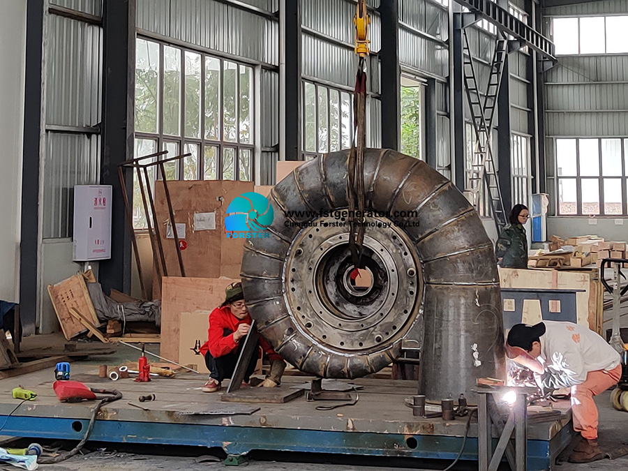
Welding: Large turbines are too big to be cast or forged as a single piece. Sub-components are welded together by certified welders using automated or robotic processes. For example, a Francis runner is often fabricated by welding individual blades onto a crown and band. Post-weld heat treatment is essential to relieve residual stresses.
2.3 Quality Control and Finishing
Quality assurance is paramount at every stage.
Non-Destructive Testing (NDT): Techniques like Ultrasonic Testing (UT) and Dye Penetrant Inspection (PT) are used to detect internal or surface flaws in welds and castings.
Balancing: The assembled runner undergoes high-precision dynamic balancing. Any imbalance can cause catastrophic vibrations at operational speeds. The runner is spun in a balancing machine, and minute amounts of material are added or removed until it rotates perfectly smoothly.
Coating: To enhance erosion and cavitation resistance, critical areas of the runner, especially the leading edges of the blades, may be coated with hard-facing materials or stainless steel weld overlays.
The Future: Trends in Turbine Design and Production
The industry is continuously evolving, driven by the needs for flexibility, environmental friendliness, and cost-effectiveness.
Digital Twins: Creating a virtual replica of a physical turbine allows for real-time monitoring, predictive maintenance, and performance optimization throughout its lifecycle.
Additive Manufacturing (3D Printing): While not yet used for full-scale runners, 3D printing is revolutionizing the production of complex prototypes, investment casting patterns, and replacement parts, reducing lead times.
Fish-Friendly Designs: There is a growing emphasis on designing turbines that allow for safe fish passage, with modified geometries and slower rotational speeds to minimize injury.
Variable-Speed Technology: Modern turbines, especially in pumped storage, are being designed to operate at variable speeds, allowing them to optimize efficiency across a wider range of power outputs and provide better grid stability.
Post time: Oct-09-2025
